


Success. Applying Continuous Infrared Camera Technology and Software at Pudget Sound Energy
19th Feb 2025
Successfully Applying Recent Breakthroughs in Continuous Infrared Camera Technology and Software to Longstanding Challenges in Safety and Production at Puget Sound Energy
By Ryan Severe
1. Abstract:
This paper examines the successful implementation of stationary infrared camera technology in wind turbines at Puget Sound Energy, demonstrating its effectiveness in enhancing workforce safety, increasing operational efficiency, and preventing arc flash and fires within nacelle environments and other electrical enclosures.
2. Introduction:
Wind turbines, a cornerstone of renewable energy, face significant risks and challenges. An average of 117 documented turbine fires occur annually worldwide, with many others going unreported due to their remote locations and the lack of centralized reporting mechanisms. These fires are the second most common cause of turbine incidents globally, after blade failure, with the fires resulting in a total loss 90% of the time. [4] Additionally, OSHA has documented incidents involving falls, electrical shocks, and arc flashes, which remain significant risks for workers in the industry. Wind turbines are strategically placed in offshore, mountainous, or open plain locations to capture strong wind patterns. However, these environments sometimes present significant maintenance challenges. Inside the nacelle, the housing for essential components like medium-voltage cabinets, issues such as overheating can lead to arc flashes and electrical fires, resulting in long downtimes due to damage to critical components. Costly repairs, operational disruptions, and safety risks for technicians are a daily challenge.
3. Wind Turbine Nacelle Maintenance Challenges:
Medium-voltage cabinets in nacelles frequently overheat due to compact component layout designs and heavy electrical loads. Components such as cables, wiring, and contactors can exceed their safe temperature limits. Overheating, fires and arc events in one component often damages nearby parts, leading to increased repair costs and extended downtime.
Diagnosing problems in wind turbines have historically been dangerous, challenging and inefficient. The turbine must always be shut down and put into local control before anyone can be in the tower or climb into the nacelle. Technicians must work in pairs. They are equipped with personal protective equipment (arc flash clothes and fall protection), and must climb to the nacelle, often in adverse conditions. Most cabinets must be isolated and de-energized before technicians can even open a door to perform their inspections. By the time they reach them, overheated components have cooled, or parts are often burned and/or destroyed, making root cause diagnosis almost impossible. Once the damage is assessed, they descend the tower to collect replacement parts before climbing to the top (often multiple trips are needed). These inefficiencies make for extended repair timelines, increase worker risks and operational costs, and reduce wind farm efficiency.
At Puget Sound Energy, we experienced many of these issues with our V80 Power Factor Correction contactors which was one of the leading causes of downtime across our Vestas fleet. We were perplexed by the many pre-mature failures of these contactors. While the manufacturer told us we should expect to see 100,000 operation cycles, we were experiencing an average life of 11,000 operations. We also suffered minor fires and electrical arc blasts and regularly faced repeated failures every one to three months.
Discovering the causation of these events would prove difficult. We understood high temperature (heat) was a major factor, but finding the source of this extreme heat was a puzzle.
Our experience told us to suspect the following issues:
1) Component orientation (was there friction from gravity or moving parts?)
2) Workmanship of the component installation (were terminations tight?)
3) Wire ends with or without ferrule (were they not fully seated or was there deformation of the ferrule?)
4) Were the contactors not sized appropriately for the application?
3.1 Investigating:
In our effort to find the root cause, the team at Puget Sound Energy undertook a step-by-step investigative process. We began by using traditional methods for measuring excessive heat.
Contactors, being the point with the highest likelihood of failure, are where the investigation began using passive, adhesive-backed temperature strips placed directly onto the contactors. This required us to shut down, isolate and de-energize the nacelle, climb the tower, place strips on each of the twelve contactors, and then descend. The units were then powered back up for a period. This was followed by a repeat of the process to collect the strips. The results were not what we’d hoped. The strips lacked timestamps, were single-use, and often failed to stay in place. We saw no anomalies and learned nothing of value.
We moved on to another traditional method - thermocouples with data loggers. These tools allow for monitoring temperature trends over time. Again, we were forced to shut down, isolate and de-energize before the ascent. In the cabinet, we encountered limited mounting locations to install our thermocouples as we needed to avoid moving parts or compromising the contactor operation and space was tight. Additionally, each data logger supported only eight channels so two were required to monitor all twelve contactors. After the technician’s descent, the power was restored, and we waited again before shutting down, isolating and de-energizing, retrieving the dataloggers and downloading the data. Overall, the results were disappointing. Like the strips, these sensors often failed to stay in the desired location. While waiting, we had no way of knowing if the data loggers were functioning properly. As it turned out, occasionally they would lock up and stop recording but we could not see this in real-time and thus ended up with missing data. Again, we found we were getting little useful information, so we moved to data loggers with a local network connection. The addition of network connectivity allowed for real-time data monitoring and verification that the loggers were actively recording. Unfortunately, the data was very limited and didn’t provide much help.
Given these challenges, traditional inspection methods proved inadequate. We needed a more efficient, real-time, and reliable way to monitor electrical components without requiring frequent, risky physical inspections. This led us to explore advanced fixed infrared camera technology.
4. A Novel Approach:
We knew we needed a better method.
A long-standing provider presented us with the idea of using new, fixed infrared camera technology.
We were skeptical at first. While the use of handheld infrared cameras has become common for predictive maintenance for electrical systems these units require a trained thermographer and often lead to inconsistent information. [7] Human errors, including calibration issues, reflective sunlight, timely inspections and misinterpretation of data often cause issues to be misdiagnosed. They are a spot in time measurement without a way to continuously monitor and to view a panel under power, you need a specialized viewing window with direct access to the fully operational panels. This is not possible in the nacelle of a wind turbine where the power must be off to physically access the cabinet.
We were assured that the new technology was simple and did not require special training and allowed for continuous remote viewing of the images in real time.
4.1 Fixed Infrared Camera Technology
We were presented with a new-to-market camera from Infrared Inspection Systems (now called Sytis). The TC-90™ Card Camera promised to solve all the issues of the past.
4.2 The TC-90™ card camera features:
- Installation and retrieval of data requires a single assent and descent of the turbine tower, substantially increasing safety by minimizing the exposure risk to collect useful data.
- Bi-spectral imaging. This is a two-camera system. Their radiometric IR camera is paired with a high-res optical camera companion that works well in low light for easy viewing and comparison for quick orientation.
-The unit is magnetically attached to the panel door. This magnet allowed us to easily move the camera around to an optimal location and fully install it without damaging the panel door.
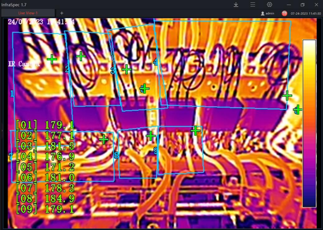
- An extremely wide field of view. It allows a single camera to clearly see at least six of the twelve contactors in one frame with the door closed. We had visual feedback on each part of the components including the housing and all termination points/wires while in full load.
-The power over Ethernet (POE) feature meant we only needed to route an existing Ethernet cable to the camera to both power and send high-res images through the local network to our desk-top in real time. It’s extremely low voltage is not an electrical hazard so no UL approval is required. -Compact, low-profile design. It easily fits into the tight space between the panel door and the electronics.
- Intuitive InfraSpec™ software with alarm thresholds that can be configured to trigger snapshots or recordings when components exceed thermal design limits. This allows immediate and actionable feedback through high temperature or temperature comparison alarm.
- The camera requires no thermography training. Clear instructions from the manual and a short time with the Sytis team got us started.
- Reasonable price. Each camera is priced around $3k each which includes all software needed to configure and operate all features of the camera.

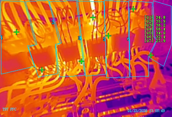
 Fig. 2 – Rotated 90 degrees, a screen shot of live stream showing side by side comparison from the Sytis TC-90™ bi-spectral camera attached to the panel door inside of a Vestas V80 PFC cabinet at Puget Sound Energy.
5. Proving the Concept:
The TC-90™ turned out to be a game changer for us as it allowed safe viewing and monitoring of 6 of the 12 contactors including the contactors, wires and terminations, while running at full power. It delivered very valuable data in real time which had never been available to us in the past. This, in turn, instantly allowed us to find that the lead wires connected to the contractors as well as the contactors themselves were operating far above their respective manufacturer’s rating. Temperatures were consistently reaching over 110°C and, on a few occasions even exceeded 180 °C whereas the manufacturer’s rating is only 90°C and 75°C respectively. We could not have discovered this specificity without this camera system.[7]
Understanding this was a design flaw in the system, we addressed the problem by mitigating the risk. We installed din rail spacers to improve airflow around contactors and installed heat exchangers on the outside of the cabinet door. This reduced the failure rate and severity of failures by improving the operating conditions of the PFC components closer to within their design limits and in turn reduce turbine downtime as well as unscheduled repair visits by technicians. The overall effectiveness of this retrofit is still being determined on a subset of turbines however short term monitoring has confirmed an average temperature reduction of 25°C. While this doesn’t fix the root cause of the problem, it allows us to closely monitor the situation and manage the issues before they can get out of hand. We are also able to easily identify any new anomalies caused by workmanship or damaged/degraded components. The image below is an example of an individual contactor that needs inspected/replaced due to possible worn contacts.
5.1 Advantages we found by using the TC-90™ fixed IR technology:
-
For the first time we are inside a fully operational electrical panel with both optical
and IR high-res clarity. -
We have cut the risk from tower climbs in half.
-
IR cameras see the important anomalies (due to increased temperatures) that the
naked eye cannot and convert it to actionable data and images. -
The InfraSpec™ software design and pre-set alerts means no one needs to be
present or watchful while the camera is working 24/7, freeing up manpower to address other tasks. Email alarms are sent to pre-determined email addresses. -
Historical records are kept of both the optical camera and the infrared cameras.
Alarm logs (with video and still shots) are also simple to access. -
Thermographer errors and training is not an issue.
-
We have substantially lowered the electrical exposure risk factor to all PSE
personnel as well as contractors working in or around our equipment. Remote monitoring allowed site engineers to safely evaluate and confirm concerns in the turbine PFC cabinet.
5.2 Measurable Safety Results:
- Overall, the installation of this product in our nacelles will likely reduce the number of trips up and down wind generation towers by several hundred per year.
- We estimate a more than 50% reduction in our need to open contactor cabinets for inspection and bi-annual preventive/predictive maintenance.
6. Applying this new technology in other areas:
After the success of the camera system in the nacelle, we began to ask ourselves where there might be benefits to this product in other areas of excessive heat, fire or arc concerns.
Power inverters and converters can be fire risks if they are not properly maintained, installed, or specified. Fires can be caused by short circuits, overheating, or other electrical issues. [2,3] Puget Sound Energy has had its fair share of problems with these devices and wanted to identify and mitigate or eliminate these potential safety hazards to PSE personnel as well as any contractor. To do this we implemented policies and procedures to perform regular inspections and testing so we know and understand the current condition of the equipment. Like in the nacelle, we hoped to stop these events before they happened through actionable data and alerts.
Arc events and fires often destroy the evidence of the cause and therefore can halt a proactive approach to changing practices. We reasoned that this camera system could give us the tools and the increased safety that Puget Sound Energy and the entire energy community has been longing for.
PSE follows standards that include routine inspections and testing so we can know and understand the ongoing condition of our equipment. This allows PSE to better understand any operational or safety risks associated with the equipment. Rather than performing a semi-annual or annual assessment, these cameras provide a real-time condition assessment which significantly reduces the risk to PSE personnel as well as any contractors that work in or around the equipment. In situations where the current condition of the equipment is unknown or questionable these cameras can now be deployed and monitored from a safe distance.
We soon had a chance to test this assumption when one of our turbine power converters began having overheating issues. Temperature alarm systems within the cabinet are great at telling us that temperatures are too high, and they can automatically turn on cooling systems or shut down the system, but they fail to give a reason as to why the event is taking place or what components are the cause.
The converter in one of the wind turbines was alarming on high temperatures and blowing fuses in the DC link. During the troubleshooting process the turbine was isolated numerous times and suspected components were replaced however the problem went unresolved for two weeks. We determined that this was a great opportunity to utilize these cameras along with other test equipment. There are multiple cabinets in this system so we deployed three cameras that were attached to the tower wall focused on each of the cabinets which were left opened. We were then able to monitor all of the components via wi-fi from a laptop in a truck at a safe distance.
We remotely operated the turbine and within a short time period we witnessed temperatures on the body of the fuses continually climb from 60°C up to 240°C before the fuse physically failed (the ceramic housing cracked open). We also saw that the center delta module and reactors were also getting hot. The delta module was replaced, however the problem persisted. Further troubleshooting led us to a defective control board that was installed during the initial troubleshooting stage. Once that was replaced, we had no further issues.
Using the TC-90™ camera system, helped us solve this issue in a matter of hours, what had gone unresolved for over two weeks. We were able to monitor the panel from a safe distance while we powered up.
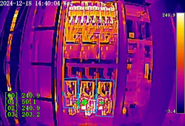
Fig. 5 - Initial view of the converter cabinet with 3 preset boxes. There are 2 fuses in each of the two boxes on the right. Fuse design limits are near 125°C. The left box [01] has no fuses and is 50°C. The right pre-set box [03] shows fuses at 203.2°C. The middle box [02] is running at 240.9° C just before the fuse failed.
 Fig 6. - Camera view after being moved closer and rotated to 90 degrees. This image shows four new presets looking at the four fuses in the two hot areas separately. Temperatures rose to 182.1C in a matter of minutes, forcing us to stop power before the temperatures rose any higher and before fuses could fail. We also noticed the middle conductors (these are DC cables) were running hot.
7. Future Applications of Fixed Thermal Imaging Technology:
This technology has already revolutionized the way we diagnose issues by allowing us to safely look inside any low, mid or high voltage system while keeping our technicians out of harm’s way. We believe this system should be considered an essential tool in all situations where ongoing electrical maintenance is required.
Switchgear is just one electrical system that comes to mind. Switchgear failures are something that should be constantly watched out for. They usually fail due to one of four issues, including loose connections, water intrusion, breaker racking, and insulation breakdown. Proper maintenance and regular inspections by a professional are recommended.[1] and traditionally done using handheld equipment. Voltage meters and handheld infrared cameras can give misleading results and put technicians in potentially dangerous situations. Use of the proper fixed IR camera system is the best way we’ve seen to continuously thermally monitor for all four of these issues without putting people in a compromising situation.
As the use of fixed thermal cameras becomes commonplace in the wind industry and AI software improves, thermal imaging will expand its utility. Beyond detecting overheating of specific components, cameras like the TC-90™ are already being used in nacelles to identify hydraulic fluid leaks by detecting the evaporative cooling of the oil leaking out. Detecting water ingress is another common use. This technology can even be used to detect mechanical stress to pinpoint components nearing failure, allowing for proactive replacements before costly breakdowns occur. AI-driven analytics will enhance predictive maintenance by monitoring trends such as vibration patterns as well as temperature fluctuations. For renewable energy systems like solar farms or hydropower facilities, these analytics will optimize equipment performance and reliability on a broader scale.
Our team is convinced that this technology is a significant part of the future of safety and predictive maintenance. And our goal is to share our success and help spread the word to keep others safe and the grid up and running. This is the new standard at Puget Sound Energy.
8. Conclusion:
Continuous thermal imaging with infrared cameras has helped to overcome the hurdles involving wind turbine maintenance by addressing critical challenges with enhanced efficiency and safety. Tools like the TC-90™, empower operators to stay safe while helping to prevent failures, reduce the need for handheld infrared cameras and costly thermography training.[5] minimize downtime, and enhance overall reliability through its remote accessibility from the safety of an office computer. The successful implementation of this technology in multiple use cases supports broader adoption of these methods across the wind generation process and in other types of energy generation. It could save thousands of trips into turbine towers and hundreds of thousands of exposures to electrical panels. As technologies like AI and advanced imaging continue to develop, thermal imaging will remain a cornerstone of sustainable and efficient renewable energy systems. AI is only as good as the information it is provided.
Works Cited:
1. Editor. “4 Major Causes of Switchgear Failure and How to Avoid Them.” Mes.com.sg, 16 Nov. 2021, www.mes.com.sg/2021/11/16/4-major-causes-of-switchgear-failure-and-how-to-avoid-them/.
2. Firetrace International. “What Causes Solar Inverters to Catch Fire?” Firetrace.com, 2022, www.firetrace.com/fire-protection-blog/what-causes-solar-inverters-to-catch-fire.
3. Fischer, Katharina, et al. “Exploring the Causes of Power-Converter Failure in Wind Turbines Based on Comprehensive Field-Data and Damage Analysis.” Energies, vol. 12, no. 4, Feb. 2019, p. 593, https://doi.org/10.3390/en12040593. Accessed 20 Oct. 2020.
4. Firetrace International. “The Wind Turbine Fire Problem, by the Numbers.” Www.firetrace.com, 12 Feb. 2019, www.firetrace.com/fire-protection-blog/wind-turbine-fire-statistics.
5. Hirschbold, Markus, and Dominique Chabert. Beyond IR Thermography: How Continuous Thermal Monitoring Improves Performance and Equipment Protection. Schneider Electric, 2022.
6. Kihn, Manfred. “Thermal Imaging Limitations.” Fireapparatusmagazine.com, 2023, www.fireapparatusmagazine.com/equipment/thermal-imaging/thermal-imaging-limitations/.
7. You, Fei, et al. “Fire Risk Assessments and Fire Protection Measures for Wind Turbines: A Review.” Heliyon, vol. 9, no. 9, Sept. 2023, p. e19664, https://doi.org/10.1016/j.heliyon.2023.e19664. Accessed 30 Oct. 2023.
About the Author:
Ryan Severe is a Senior Plant Engineer for Puget Sound Energy in Washington State where he has worked for eighteen years. There, he oversees the PSE's 384 wind turbines over three separate facilities along with the associated substations and SCADA Monitoring Systems. Ryan is dedicated to finding innovative ways to improve safety while lowering the cost of O&M and sharing his experience and insights with the wider wind energy sector across the globe.
Share:


